GPS as a Time and Frequency Standard
In part 1 of this series, I described the strengths and weaknesses of crystal oscillators. The moral of that story was that a number of processes affect a crystal’s frequency, and that you need something to calibrate and measure the XO against. I hinted that the GPS system might provide an answer. So let’s see if that’s correct.
GPS as a Time Source
Since the 1990s, we’ve had a way to generate incredibly accurate time signals from small and low cost hardware.[1]Small and low cost today; soldiers wore the first GPS receivers as backpacks, and they cost over $10K. Things have advanced a lot since then. That’s because satellite navigation systems such as GPS use trilateration to work out the receiver’s position based on its distance from several satellites orbiting overhead.
If you know precisely where each of those satellites are located in the sky, and precisely when each starts its message transmission sequence, and you also know that light (and radio waves) travel about 300,000 km/h, you can calculate how far you are from a satellite by measuring the delay between the known message start time and when you actually get it.
Now, since you know exactly[2]Well, not exactly — there is always a little error, just as there is always a little error in the time measurement. But you can get amazingly close where the satellite is and how far away it is, you can draw a circle centered on the satellite with a radius equal to its distance from you. You are somewhere on that circle. If you do that for several satellites, the place where the circles intersect is where you are.
Why is this interesting to time-nuts? To make the navigation system work, the satellites have onboard atomic clocks that provide the timing of their signals, and those clocks are steered by ground control to remain within a few billionths of a second of the US Naval Observatory official time. So the clocks up there in space are extremely accurate.
To do its work, the GPS receiver in your hand reconstructs the GPS time tick against which to measure the satellite signal arrival time. As a by-product of that, some receivers provide a pulse-per-second (PPS) signal output that’s locked to the satellite clocks.[3]Most consumer-oriented GPS receivers don’t provide access to the PPS output, but board-level GPS modules that do have one are available from many sources, like AdaFruit and SparkFun.
This PPS output is both very accurate (tracks the “true” time very closely) and has the same long term stability (runs at the same rate over long time periods) as the USNO’s master clock . The PPS output of moderate-cost GPS modules can be within less than 100 nS of USNO time, and the interval from pulse to pulse can be constant within better than 10 nS.
Since GPS provides precise time, and time is the inverse of frequency, the PPS signal is actually a 1 Hz signal generator. That may seem both obvious and not all that interesting, but it’s a concept that will become important later.
However, there ain’t no such thing as a free lunch. Just like crystal oscillators, the GPS PPS signal has some disadvantages. The main one is jitter (or noise) on the PPS output. Changing ionospheric delays, limitations in the GPS receiver’s hardware, and other factors make the PPS signal from the receiver bounce around quite a bit from second to second.[4]“Quite a bit” is relative — the jitter can be as low as a few billionths of a second. But that’s quite a lot to time-nuts When averaged over minutes/hours/days the accuracy is extremely good, though.
Differing Strong Suits
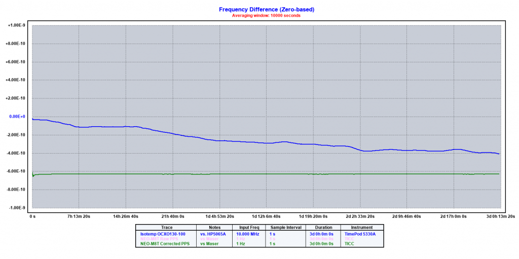
To show the advantages and disadvantages of each type of frequency source, the plots below show the frequency variations of an inexpensive OCXO (the blue trace) and a moderate-quality GPS receiver (the violet trace) over time periods of a few minutes (top) and three days (bottom). Look closely and you’ll see that the vertical scale of the two plots is different — the top one covers 30 times more frequency variation than the bottom one — so keep that in mind as you compare them.
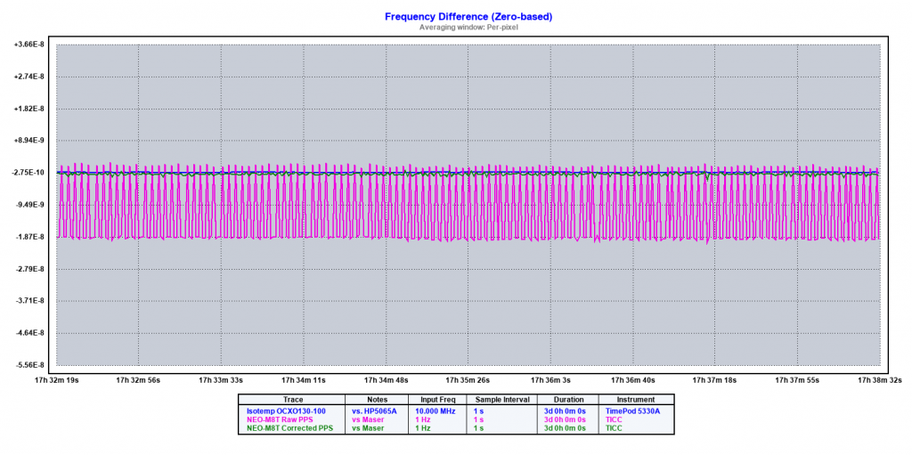
In the first plot, note the zig-zag pattern of the PPS signal compared to the very smooth trace of OCXO. The jitter covers a range of about 40 nanoseconds (or 40 billionths of a second[5]or 40 parts per billion (PPB ). That’s a real problem for short term measurements because you don’t know precisely where the pulse will occur from one second to the next.
If you used this signal to clock a frequency counter measuring a 100 MHz signal, it would cause second-to-second changes of about 4 Hz. Depending on what you’re doing, that might be a lot or not enough to worry about.
The second plot shows that over longer periods the GPS signal (here, green) stays flat while the OCXO (blue) is drifting downward in frequency, with some bumps and dips along the way.[6]The GPS data shown here is a slightly processed version of the trace shown in the first plot. This was necessary to get the two traces to align on the graph. The frequency of the 10 MHz OCXO is changing about -0.00001 Hz (or -10 uHz) per day. Again, in some ways that’s not much, but remember that it accumulates over time: a couple of years from now, the frequency error might become significant. And if you’re looking at a 1 GHZ signal, that drift is now 1 milliHz per day.
Making Use of the GPS PPS
So, what can we do with this knowledge? The GPS signal is no good to measure short term noise, because it’s likely orders of magnitude noisier from second to second than any XO. But by averaging the GPS pulses over tens, hundreds, or thousands of seconds, we can determine the absolute frequency, and the long term stability, of an oscillator to extremely high precision.
A simple way to use GPS to set the frequency of an XO is to use an oscilloscope. There are several methods, depending on the type of scope.
If you have a digital scope, the easiest is to hook the GPS PPS to channel 1 and trigger from that. Set a slow sweep speed so you see several pulses on the screen. Now connect a pulse from your XO to channel 2 — it’s best to use a PPS signal, but it can also be done with a MHz-range sine wave, though it only works well if the two signal are very close in frequency).[7]There are some simple and inexpensive circuits that will generate a PPS signal from a 5 or 10 MHz XO. One is the TAPR TADD-2 Mini.
The GPS PPS pulses on channel 1 will be stationary, and the signal on channel 2 will walk across the screen. Adjust your oscillator until its signal remains stationary, or as close to stationary as you can get, for several seconds.
If you have an analog scope, it is hard to see signals at very slow sweep speeds. In that case, there’s another method called the Lissajous pattern that you can use. The link above is a good reference that goes into more detail than I have room for here.
There are other ways to use GPS signals to measure the frequency of oscillators, but there’s a next step — using GPS to control the frequency of an oscillator. That’s what makes a GPS disciplined oscillator (GPSDO) and in part 3 of this series, we’ll look at how that’s done.
References
| ↑1 | Small and low cost today; soldiers wore the first GPS receivers as backpacks, and they cost over $10K. Things have advanced a lot since then. |
|---|---|
| ↑2 | Well, not exactly — there is always a little error, just as there is always a little error in the time measurement. But you can get amazingly close |
| ↑3 | Most consumer-oriented GPS receivers don’t provide access to the PPS output, but board-level GPS modules that do have one are available from many sources, like AdaFruit and SparkFun. |
| ↑4 | “Quite a bit” is relative — the jitter can be as low as a few billionths of a second. But that’s quite a lot to time-nuts |
| ↑5 | or 40 parts per billion (PPB |
| ↑6 | The GPS data shown here is a slightly processed version of the trace shown in the first plot. This was necessary to get the two traces to align on the graph. |
| ↑7 | There are some simple and inexpensive circuits that will generate a PPS signal from a 5 or 10 MHz XO. One is the TAPR TADD-2 Mini. |
3 comments
[…] We’ll start with understanding the strengths and weaknesses of crystal oscillators, then in part 2 see how GPS can be used as a frequency standard. In part 3, I’ll compare XO and GPS […]
[…] part 1 and part 2 of this series, we saw that crystal oscillators and GPS receivers both have strengths and […]
[…] far in this series, we’ve seen the strengths and weaknesses of both crystal oscillators and GPS receivers, and then compared those […]