Enter the GPSDO
So far in this series, we’ve seen the strengths and weaknesses of both crystal oscillators and GPS receivers[1]I mentioned in part 1, but it’s time to reiterate — I’m using “GPS” generically. It’s perfectly possible to use the GLONASS, Galileo, or Beidou satnav systems to discipline an oscillator, but a large majority of currently available DOs use GPS., and then compared those characteristics.
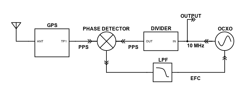
Now, just as Reese’s joined chocolate and peanut butter together, we’ll combine a crystal oscillator and GPS to take advantage of each one’s best qualities. The result is a GPS disciplined oscillator, or GPSDO. Here’s a block diagram of a typical design; below I’ll describe the components, what they do, and how they work together.
The idea behind a GPS disciplined oscillator is that a control loop, usually a phase locked loop, compares a PPS[2]Sometimes other frequencies are used for the comparison. signal derived from an OCXO[3]Sometimes a TCXO or even an atomic standard is used. and generates a control voltage[4]Some system use a digitally controlled oscillator. that steers the OCXO to keep it locked to the average frequency of the GPS PPS.
That word average is really important, because if the OCXO tracked every second-to-second wiggle in the GPS signal, nothing would be gained — we’d just be transferring the GPS noise to the OCXO. We need to slow down the adjustments so that the OCXO tracks the GPS frequency over the long run, while filtering out the short term GPS noise. But we don’t want to slow things down so much that the oscillator drifts off frequency before the GPS can correct it.
Here are the main components in the drawing above:
- From the left, a GPS receiver provides a pulse-per-second (“PPS”) signal locked to the GPS system atomic clocks.
- From the right, an oscillator a user output, as well as driving a divider that generates a PPS signal. (Often, that PPS signal is also made available to the user.)
- In the middle, a phase detector compares the relative timing of the two pulses, and generates a control voltage proportional to their difference.
- That voltage is low-pass filtered to remove the short-term GPS noise. The filter is usually implemented digitally by a microcontroller, but could be a really big capacitor and resistor.
- The filtered control voltage adjusts the OXCO’s frequency to follow the average frequency of the GPS system. It’s usually fed to the oscillator’s electronic frequency control (“EFC”) input, but some modern oscillators use digital control.
That’s all there is to it. The magic is in the way the control loop is tuned to extract the best from each signal source. There are several parameters that need to match the characteristics of both the GPS receiver and the OCXO. The main ones are:
- Most important, the loop time constant or bandwidth[5]The time constant of a filter is the inverse of its bandwidth; a time constant of 1000 seconds is the same as a bandwidth of 0.001 Hz. With very narrow filters it seems more intuitive to talk about time constant than bandwidth. determines how quickly the control voltage follows the GPS signal. Too short and the GPS noise is passed through to the oscillator; too long and the OCXO starts to drift away from the stable GPS frequency.
- The loop damping affects how the loop responds to transients like a sudden noise burst.
- Finally, the control system needs to know the OCXO frequency change per unit of control voltage change. This is the oscillator’s EFC sensitivity , and the adjustment resolution must be small enough to smoothly tune the oscillator without noticeable jumps.
Choosing the optimum time constant is really critical for best GPSDO performance. The general rule is, the better the OCXO, the longer the loop time constant. If it is too short, control will be handed to the GPS while the OCXO is still able to handle the job. If it is too long, drift will reduce the performance before the GPS control kicks in.
Here are plots from a surplus Trimble Thunderbolt[6]The Thunderbolt is beloved by Time-Nuts because its loop parameters are accessible and tweakable. That leads to hours of educational play time. measured with time constants ranging from 50 to 500 seconds.
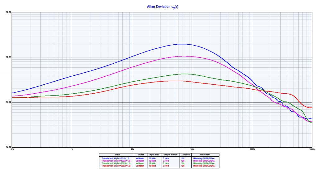
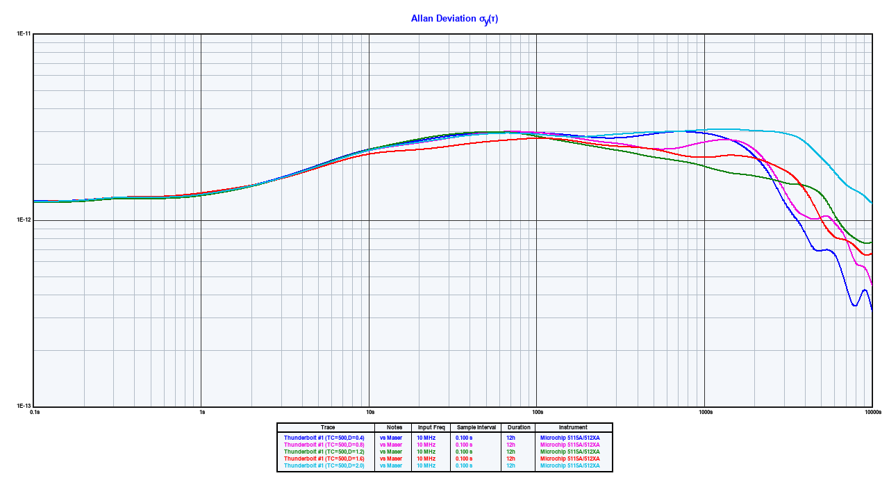
The Thunderbird OCXO is pretty good, so a longer time constant is appropriate. The 50 second constant gives an ADEV peak almost an order of magnitude higher than the 500 second one. 1000 seconds might work better still.[7]I also measured this Thunderbolt with different damping values. The differences aren’t that exciting, but you can see the results in this plot.
Now, let’s tie things together by looking at a few GPSDOs compared to our old friends the u-blox NEO-M8T GPS and Isotemp OCXO131-100.
Once again, the GPS PPS is the blue trace, and the free-running OCXO is the violet one.
You can see that each of the GPSDOs shows the characteristic ADEV hump, but there are some very noticeable differences. Here are some details about each of the three units:
- The green trace is an inexpensive BG7TBL GPSDO, widely available on eBay from several Chinese vendors. The BG7TBL plot is interesting because it seems to flatten out and not keep improving as the others do. This could be related to this unit’s use of a frequency lock loop rather than the more typical phase lock loop. (Some versions of this GPSDO have performance issues that may also be related to the FLL; my posting at https://blog.febo.com/?m=202207 goes into that.)
- The orange trace is the Trimble Thunderbolt that we saw above, running with its default settings.
- Finally, the cyan trace is a surplus HP/Agilent/Symmetricom Z3805A that has the best short term stability of the bunch thanks to its excellent OCXO. Note that its loop time constant is longer than the others, probably a couple of thousand seconds. It’s a very good GPSDO.
We’ve seen that the GPS system and an oscillator can be combined to create an extremely accurate and stable frequency reference. There’s nothing exotic in the technology and quite a few hobbyists have built their own units, often implementing the control system with inexpensive microcontrollers like the Arduino.[8]Here’s a thread about a nice one designed by Lars Walenius that’s been the basis for several later designs. Hopefully this series has helped you understand how they work, and why they’ve become the most common frequency reference in use today.
Is that all there is to say about GPS and freuqncy control? Well, stand by as there may be a part 5 of this series soon. </teaser>
References
| ↑1 | I mentioned in part 1, but it’s time to reiterate — I’m using “GPS” generically. It’s perfectly possible to use the GLONASS, Galileo, or Beidou satnav systems to discipline an oscillator, but a large majority of currently available DOs use GPS. |
|---|---|
| ↑2 | Sometimes other frequencies are used for the comparison. |
| ↑3 | Sometimes a TCXO or even an atomic standard is used. |
| ↑4 | Some system use a digitally controlled oscillator. |
| ↑5 | The time constant of a filter is the inverse of its bandwidth; a time constant of 1000 seconds is the same as a bandwidth of 0.001 Hz. With very narrow filters it seems more intuitive to talk about time constant than bandwidth. |
| ↑6 | The Thunderbolt is beloved by Time-Nuts because its loop parameters are accessible and tweakable. That leads to hours of educational play time. |
| ↑7 | I also measured this Thunderbolt with different damping values. The differences aren’t that exciting, but you can see the results in this plot. |
| ↑8 | Here’s a thread about a nice one designed by Lars Walenius that’s been the basis for several later designs. |